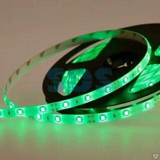
The 12v led strips are low voltage. 220V is an electric current designed for civilian use. It is also possible to say that the input voltage of 220V is the same as the working voltage, which is 12V.
The 220V light strip is convenient and can be directly connect-ed to the 220V power supply However, it is not secure.
The LED strip with low voltage lights is safer. When connecting them you must connect a transformer prior to when it can be connected to the power source.
The 220V connector for light strips comes with an internal converter that includes a rectifier with constant current output. The voltage that is produced by the rectified and the filtered plug is 300 volts DC.
It regulates the output voltage by constant current conversion to 10 milliamperes DC for driving the LED light strips. The light strip with 12V power does not have a power converter inside and the power source 12V DC is directly input to drive the LED light strip.
LED Selection Parameters as well as 12v Direct Drive Led Strip Lights
Let me ask you a question: Could 12V power a light-emitting diode directly, in conjunction with resistors?
The operating current for low-power LED lamp beads in a variety of shades is typically 20mA however, the actual number is 5 to 15mA.
For low-power red LEDs the forward voltage drop is 1.6~2V, green ones are typically 1.8~2.4V, and blue and white are 3~3.3V.
Let’s suppose that a blue lamp bead is drive-n with a 12V power source and the operating voltage is 9mA. Then, the resistor that limits current R equals (12V-3V/9mA) = 1KO. The voltage drop forward for the blue lamp is 3V.
I picked an LED however, I encountered some issues when driving it. While the light isn’t as high as a tri-color light but I can only see red,
The parameters are shown below the 3535MWAP from Nationstar Optoelectronics was chosen as the ‘d.
IF: is the forward current that refers to the current that is generated when the LED strip light is operating. The working current for ordinary dimmers emitting light is typically very low, ranging from 10mA to 45mA.
When the voltage is increased, the current will increase to an enormous extent therefore light-emitting diodes are connected with protective resistors.
lD: wavelength.
The different materials used in the die may produce various colors.
The luminescent color of the same substance can be altered by altering the impurities, their concentration, or composition.
The table below illustrates the luminescent substances used in LEDs with different colors.
Use of Luminous Color Material Wavelength
Ordinary red GaP 700
High Brilliance Red GaAsP 630
GaAlAs Super bright red
AlGaInP Super bright red 625-640
Green in the normal sense GaP
High Brilliance Green AlGaInP
Super bright green InGaNg 505-540
Ordinary yellow GaAsP 590-610
Super bright yellow AlGaInP 590-610
Light intensity IV
The luminescent flux produced by the lightsource within a unit solid angle is call-ed the light intensity I of the light source.
The measurement of intensity is known as candela (cd) which is usually used in conjunction with millicandela (mcd).
One lumen of light emitted within one solid angle is known as one candela. Candela is the luminous power of any light source that is located in a given direction.
VF: forward voltage
Forward voltage is the term used to describe the voltage drop produced between the positive and negative electrodes if the forward current running through the LED has a specified value, represented with the symbol VF.
Our company utilizes SMD LEDs with the forward voltage of 2.0V up to 3.5V.
If it is greater than the operating voltage of normal the diode can be destroyed. If the forward voltage is below a certain threshold (also known as the threshold value) the current becomes extremely low and there isn’t any light emitted.
If the voltage is higher than some level then the forward voltage increases with the voltage.
The light isn’t correct because the voltage drop measured forward is merely few Volts.
View angle: perspective
In the luminous intensity distribution graph the angle created by an intensity equal to half of the maximum intensity is called the half value angle.
In Figure 5>.
In the diagram, the normal direction of the LED is the direction of the mechanical axis. the direction of the highest luminosity is the direction of the optical axis and the angle between the mechanical axis and optical axis becomes the deviation angle.
The half-value angle is directly affected by the thickness of the chip and the size of the mould strip.
When manufacturing, different dimensions of half-value angles can be obtained by choosing different materials and choosing different dimensions of the package based on customers’ requirements.
According to the diagram of luminous intensity distribution Three categories are identified:
High directivity is achieved by using metal cavity packaging with reflective point packaging made of epoxy or metal. This can be accomplished without the use of a scattering agent.
The half-value angles range from 5deg to less than 20deg. The high-directivity light can be employed as a source local of light or with a light sensor, to create an automated detection system.
Standard type. is usually used as an indicator with an angle of 20deg-45deg.
C scattering light has a higher view angle and a half-value angle of 45deg and 90deg.